Improving Your Charging System
By: Craig Houghtaling
02/15/98
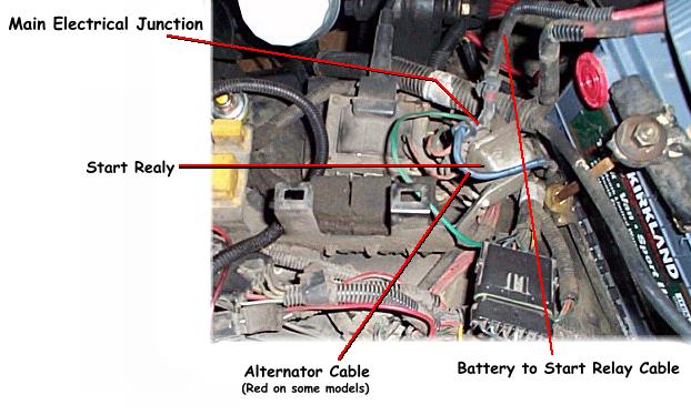
Under normal circumstances even with a good alternator in your XJ, you can expect to see a voltage drop when you use the "high draw" accessories like the A/C or heater fan, high output H4s etc. This is because the factory wiring from the alternator's output to the Main junction of the battery and electrical system, is only a 10 gauge (AWG) wire (8 AWG on later models, ...still too small). The Main junction of the electrical system (for pre '91s) is the large stud on the "Start Relay", which is located directly behind the battery under the black plastic cover that protects the Relay Center ¹(see notes below for later models). This is the main distribution point for all your vehicle's electrical circuits (except the starter), every electrical component, every accessory, even engine management, all get their power through this connection. The battery feeds this junction also with a short length of wire that is the same size (too small). This is the weak link in the charging/electrical system. It is unrealistic to expect a 100~120 amp alternator (or a battery), to efficiently run that much current through a 10 AWG wire. You have plenty of amps available, but very little flow. Think of the wire as a hose, you can't push very much water through a small hose, and you can't push very much power through a small wire. It's like hooking up a garden hose to a fire hydrant to put out a house fire! (plenty of water, ...but very little flow).In the electrical system, when the accessories draw enough current to exceed the normal capacity of the 10 AWG alternator wire, it starts to heat up, and power from the alternator starts to dissipate in the form of heat in the wire, and the result is reduced voltage at the main junction. Electricity is like water and it will take the path of least resistance. Since the accessories are still trying to draw what they need, the battery becomes the source of least resistance with its shorter length of 10 AWG cable, and has to start supplying the rest of the load, which will then start heating up this wire and dissipating power in the wire instead of supplying it to the load. With all the accessories on, the battery and the alternator put together cannot maintain sufficient voltage at the Main Junction through these little wires. This is not a good situation, and when you add high output H4s, auxiliary lights, a high watt stereo, not to mention a winch, ...it gets worse. Sure you can hook these extra accessories right to the battery, but that only guarantees you 12~12.5 volts. Lights, winches, big stereos, and other high draw accessories, perform better as the voltage increases. (Your lights can be up to 40% brighter with 14.5~15 volts). It's the alternator that has to supply the battery with voltages above 12.5 volts, and regardless of where the load is attached, the alternator still can't push enough current through that small wire to maintain a higher voltage at the battery, and the rest of the system suffers because of the extra drain. Another important thing to consider is when voltage drops current increases. This means that your accessories will try to draw more current at 12 volts than they do at 14 volts. This is particularly bad for your expensive H4 bulbs and your winch, because it can cause them to run hotter and shorten their life. Like the 4.0's cooling system, the engineers fell short of the mark in the electrical/charging department. This is not the only area in the electrical system that needs work, but that's a subject for another article.
There is however a simple solution to this problem, and it'll only cost you a few bucks. Just replace both of the 10 (8) AWG charging wires with 4 AWG or larger ²(See note on Wire Size) cables.
But wait! That's not all... the ground path is another area that can stand improvement. There is really no problem with the existing ground strap (the braided strap that connects the engine to the firewall), but there is a problem with the fact that the battery is only grounded to the chassis through the engine. Early models do not have a direct ground cable to the chassis. Because so many electrical circuits are grounded to the body, this is a bottleneck in the ground path. The quickest and easiest way to remedy this is to add a short 4 AWG cable from the battery ground post, directly to one of the small bolts (torx screw) that secure the top metal radiator support near the battery. Be sure to remove the paint from under this connection to ensure good contact with the bare metal. This will provide all the ground path your vehicle will ever need.
You can usually find the cables at your local auto parts store. You'll need an 18"~20" 4 AWG cable with 5/16" (preferred) or 3/8" lugs on both ends for the Alternator-to-Main Junction cable, and two 8"~12" cables (one red, one black) for the Battery-to-Main Junction & Battery-to-Ground cables. If you can't find the lengths you need, you can either make them yourself, or have them made (many auto parts stores can do this for you).
The factory alternator cable that you are replacing utilizes a fusible link that is incorporated into the wire. This upgrade eliminates this link and I recommend the use of a bar style fuse (available for marine and industrial applications) with a capacity equal to that of the alternator output.
These fuses come in ratings from 100 amps to 250 amps (in 25 amp increments). They are rectangular in shape (approx. 3/8"H x 5/8"W x 1-1/2"L) and have a large copper mounting lug on each end with a 5/16" hole that allows a direct bolt-up to the cable end and to the lug on the Start Relay. These bar fuses are very ridged and will work well in this application, and offer very little resistance to current flow (unlike conventional fuses). They cost $8.20 and I get them from the local marine supply (West Marine) here, but you can order them on-line from the West Marine web site, here's the link: West Marine . There is also a fuse holder available ($20) for these "Mega" fuses which you can mount to the inner fender for a very bullet proof installation. This will require an additional short piece of cable to run from the fuse holder to the Start Relay. I definitely recommend this for those up-grading to cables any larger than 4 AWG.
If you are contemplating a high output alternator, then this upgrade is a must! Otherwise all your doing is hooking your little garden hose to a bigger hydrant! ...But do the mod first before you buy the alternator, you just might find it will be enough, and you can save the money for something fun (like more lights };)
This upgrade will greatly improve your charging system and the overall performance of your all your accessories. This is especially useful for those of us with high output lighting. Remember every volt that makes it to the lights equals more light output! My voltage still reads over 14 volts with every accessory on, including my 145 watt high beams, and my 130 watt auxiliary lights. ³(See note on voltmeter)
This is a real simple modification, but if you need a little guidance click here. And please remember, the main junction is tied directly to the battery with no fuse and is HOT all the time, so always disconnect the battery prior to performing any work in this area. I also highly recommend the use of GB OXGARD on all of these electrical connections, it is well worth the small effort to get this stuff and put it on while you've got the cables all off anyway, ...read about it here. If you have questions regarding the information on this page, you may e-mail me for clarification.
¹ Later Models:
The wiring layout on models built after 1990 differs in that the main electrical junction is located on the front of the Power Distribution Center (PDC), which is mounted behind the battery. This is a large lug with a nut that secures the cable from the battery. On these models the factory alternator wire does not connect here, instead the alternator wire runs directly into the PDC to fuse locations #F8 & #F16 (labeled "60A ALT PWR1" & "60A ACT PWR2"). Even though the layout is different, these models suffer from the same problem, ...the alternator wire is too small. The removal of the existing alternator wire is not easily possible with this set up and not recommended. If the upgrade is desired, this wire either needs to be abandoned (and fuses removed), or the larger cable can be piggy-backed to the existing wire at the alternator and connected to the front of the PDC (leaving the fuses in place). The addition of the 4 AWG cable will essentially bypass these fuses so it is recommended that you install the bar style fuse mentioned above. It can be bolted directly to the junction of the PDC and the new cable can be attached to the other end of the fuse, though I recommend the use of the fuse holder in order to retain the protective plastic cover on the PDC (which may not fit properly with the fuse mounted here).Another difference in the later models was the addition of a battery ground cable. However, like the rest of the charging system, it is too small and should be replaced with a larger cable to optimize the performance of the system.
² Wire Size:
A note on wire size. Bigger is better, but only to a point. After that point, bigger is only heavier and much more expensive. For alternators under 200 amps, 4 AWG is quite adequate and 2 AWG is the biggest you need. Some people tend to get carried away with wire size. Using O AWG welding cable and bigger looks impressive, but provides no extra benefit what so ever. It's like installing a fire hose for a fuel line and expecting to get more power. Once the demand for flow is satisfied, any increase in size is no longer needed.
³ Voltmeter:
It should also be noted that the factory in-dash voltmeter is connected down stream of the headlights (and other accessories depending on the year), and does not provide an accurate indication of the state of the charging system. They are also not marked clearly enough to be accurately read, and after testing several different voltmeters I came to the conclusion they all read a little differently. The most accurate location to measure from is the main electrical junction, but this needs to be done with a VOM to verify the true voltage level. If you want to accurately monitor your charging system while driving, I suggest investing in an aftermarket voltmeter and run a wire to the main power junction with an on/off switch so you don't drain the battery when the engine isn't running.
Back to Main Page Back to Electrical Page
Questions or comments can be sent to:
dch@olypen.com

A Wizard of Wiring
Production
WoW
1998
®